
HIGH QUALITY OPTICAL COATING TECHNOLOGY

HIGH QUALITY OPTICAL COATING TECHNOLOGY

HIGH QUALITY OPTICAL COATING TECHNOLOGY
HIGH QUALITY OPTICAL COATING TECHNOLOGY
HIGH QUALITY OPTICAL COATING TECHNOLOGY
HIGH QUALITY OPTICAL COATING TECHNOLOGY
HIGH QUALITY OPTICAL COATING TECHNOLOGY
HIGH QUALITY OPTICAL COATING TECHNOLOGY
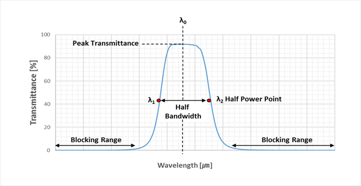
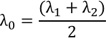
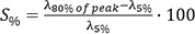
: Where λ1 and λ2 are the wavelength at 50% of band pass filter peak transmittance
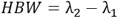
: Band width of band pass filter
: Maximum transmittance with in the band pass filter
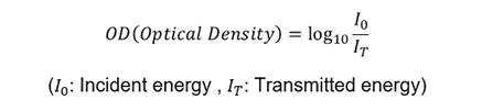
: It is the amount of energy to the total energy out side the band pass.
Commonly refer to as signal to noise ratio or it is usually express in optical density(OD)
: Band pass shape is defined to the number of cavities in a filter. The more cavity The number of cavities is defined by customer’s requirement about CWL, FWHM, Transmittance, and blocking.
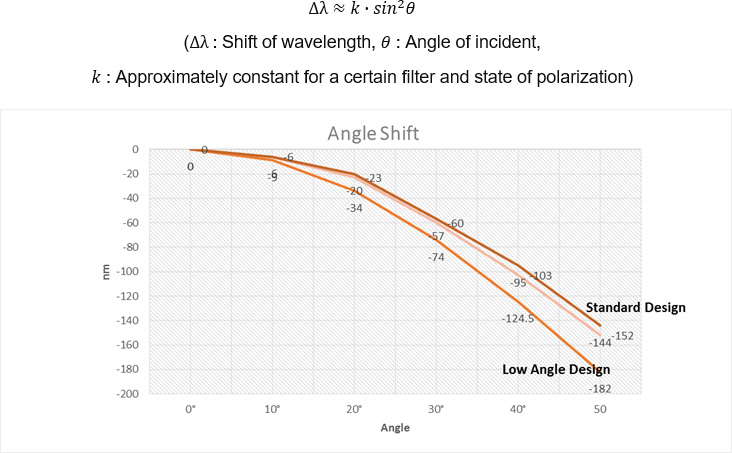
: Thin film interference filters change with incident angle. The following equation may be used to define the wavelength at a certain angle of incident.
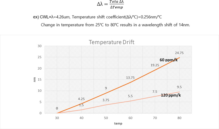
: The center wavelength will shift to a longer wavelength with increasing temperature.
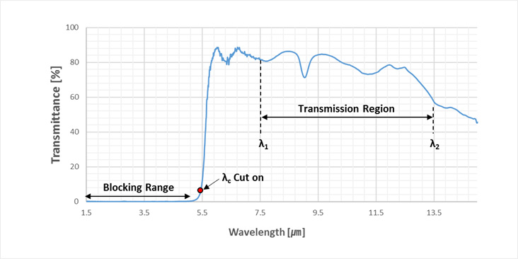
: Transmittance average from λ1 to λ2 50%
: This is the wavelength at which the edge filter begin(or end) to transmit.
About us
Development
Technical
Support